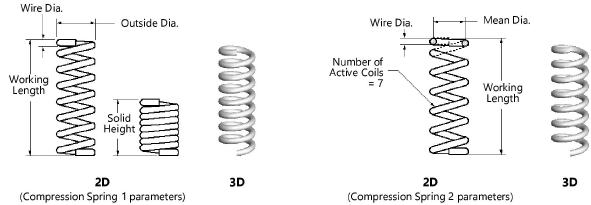
 Compression springs 1 and 2
|
Mode |
Tool |
Tool set |
|
Modes for Créer des lignes Modes for L’outil Insertion de symbole |
|
Machine Components |
Multiple compression spring tools share the same position on the tool set. Click and hold the mouse on the visible tool to open the Sous-outils list and select the desired tool.
The 2D compression springs are linear objects, while the 3D compression springs are point objects.
To insert a compression spring:
Click the tool and mode.
Click to place the object, and click again to set the rotation. The first time you use the tool in a file, a properties dialog box opens. Set the default parameters. The parameters can be edited later from the Object Info palette.

Click to show/hide the parameters.Click to show/hide the parameters.
|
Parameter |
Description |
|
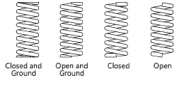
Type of Ends |
Specify the spring end style
|
|
Outside Diameter |
For Compression Spring 1, enter the outside diameter |
|
Mean Diameter |
For Compression Spring 2, enter the mean diameter |
|
Wire Diameter |
Enter the wire diameter |
|
Solid Height |
For Compression Spring 1, enter the solid height (compressed height) |
|
Number of Active Coils |
For Compression Spring 2, specify the number of active coils |
|
Working Length |
Either specify the spring working length value, or click and drag a spring control point to define the length graphically
|
|
Spiral |
Select either a Left Hand or Right Hand spiral direction |
|
Display (2D only) |
Select a display mode for 2D springs
|
|
Draw Center Line (2D only) |
Draws the spring with center line(s) |
A utility calculates spring rates for compression springs (see Spring calculator).
To simulate the appearance of a spring wound around an object (such as a shaft or screw), use two springs. Set the front spring’s display parameter to Solid - Front Coils Only. The spring behind the object is set to Solid - Rear Coils Only. Adjust the objects’ relative position with the Modify > Send > Send to Front and Modify > Send > Send to Back commands until the object displays correctly.
![]()


