 Cam design
The cam object, which is created using one of the Cam templates provided with the Vectorworks software, can be animated and generates cam data worksheets and diagrams.
The recommended procedure to include a cam in an existing Vectorworks drawing is to create it in a separate document, then copy and paste it into the drawing, and convert it to a group by selecting it and selecting Modify > Convert > Convert to Group.
To create a cam object:
Select File > New.
The Create Document dialog box opens.
Select Use document template, and choose the Cam (Imperial).sta or Cam (Metric).sta template.
For version 2019 and later, the required .sta files are located in the [Vectorworks]\Libraries\Objects - Miscellaneous_Entourage\Machine Design\Templates folder. Copy the template file you need into your [User]\Libraries\Defaults\Templates folder.
The new file opens, with a cam inserted by default. The file contains Cam and Diagrams layers. The cam object is a point object; its properties can be edited from the Object Info palette.
Click to show/hide the parameters.Click to show/hide the parameters.
|
Parameter |
Description |
|
Prime Circle Radius |
Specify the prime circle radius |
|
Cam Type |
Select plate or groove |
|
Outside Dia. |
Enabled if Groove is selected in Cam Type. Enter the outside diameter for groove cam types. |
|
Cam Drawing Incr. (Deg.) |
Enter the cam drawing increment, in degrees; this parameter affects how the cam is drawn. The larger the value, the less smoothly the cam is drawn. |
|
Cam Speed (rpm) |
Specify the cam rotation in revolutions per minute (rpm); this value is used to calculate the velocity and acceleration of the cam follower |
|
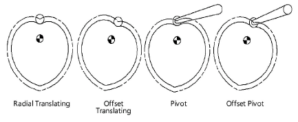
Follower Type |
Select one of the follower types
|
|
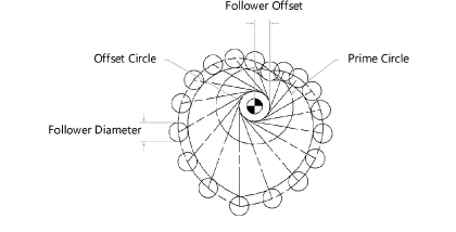
Follower Dia. |
Enter the follower diameter |
|
Follower Offset |
Enabled if Offset Translating Roller or Offset Pivot Roller is selected in Follower Type. Indicate the distance between the center of the cam and the follower center for the offset follower types. |
|
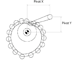
Pivot X/Y (from cam center) |
Enabled if Pivot Roller is selected in Follower Type. Specify the X and Y distance from the cam center to the pivot arm for pivot roller follower types.
|
|
Draw Followers |
Draws the followers |
|
Follower Incr. (Deg.) |
Determine at what angles to display followers by entering the follower increment in degrees (to show only the actual follower, enter 360). If a segment of the cam ends on an angle that does not correspond to the follower increment, the additional follower is also displayed. |
|
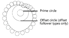
Draw Prime and Offset Circles |
Displays both the prime and offset circles
|
|
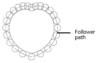
Draw Follower Path |
Displays the follower path
|
|
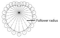
Draw Radii |
Draws a radius from each follower to the center mark
|
|
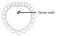
Draw Center Mark |
Draws a center mark
|
|
Data Incr. (Deg.) |
Specify the increment at which the displacement, velocity, and acceleration of the cam follower are calculated for the worksheet and text file |
|
Define Cam Profile |
Click to specify the profile of each cam segment |
|
Write Data to Worksheet |
Click to write the results (displacement, velocity, and acceleration) to the worksheet named Cam Data, using the increment specified by Data Incr. |
|
Write Data to Text File |
Click to write the results (displacement, velocity, and acceleration) to a text file using the increment specified by Data Incr. |
|
Animate |
Click to animate the cam |
|
Reset Cam to 0 |
Click to position the cam back to zero degrees; for more information, see Resetting the cam to zero degrees |

